1) Link to Blog
2) Link to Chosen Object
3) Link to Photogrammetry
4) Link to Construction of template
5) Link to Metal Mashing Trial
6) Link to Metal shaping of Chosen Object
7) Link to Final Object and Skin
Wednesday, 27 April 2016
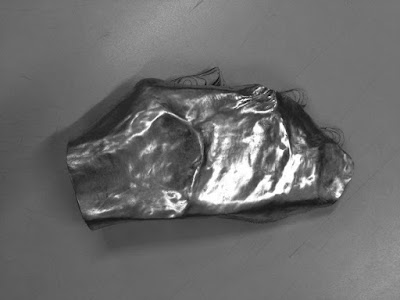
OBJECT AND SKIN
The difficulty of the chosen object was truly seen during this workshop, as it was incredibly hard to mimic the contours, shape and form of the human hand. Although the larger features of the hand such as the knuckles and wrist were able to be reproduced, the more intricate movements and details of the object, proved to be extremely hard to fabricate, especially due to the limited and small scale of sheet metal.


Chosen object - My hand

Wrist curvature of final skin

Slope of shape form

Side view of metal skin

Top view of skin showing wrist and knuckle movements

Knuckle dip and side wrapping

Front slope towards fingers

Side wrap of metal skin

Inside of skin, showing wrist and knuckle dips

Skin placed on object

Side view of skin on object

Skin with protruding fingers

Partial wrapping of side

Top view of skin over object

Final object and skin
METAL SHAPING OF CHOSEN OBJECT
The process of fabricating the skin of the chosen object was quite a complex and intricate task. Due to the meandering and contoured shape of the hand object, the task of matching these, especially such a small scale would prove to be difficult.


Firstly, a piece of aluminium metal sheeting was cut to size in order to have a base sheet. By generously tracing the shape and outline of the hand object; allowing an offset of 10 - 20 mm on each side to allow room for error and to play with, curved shape was created.

Outline of object to be cut
Following this process, the edges of the metal sheet were then shrunk and stretched, both using the machine as well as the more traditional mallet against the tree stump shrinker. Of the two methods, the tree stump shrinker, although slower, yielded results that were much more aesthetically pleasing, as the sheet metal shrinker indented lines and creases into the skin of the metal. In order to impart curvature into the form of the sheet metal, it was inverted and hit into the sandbag using a teardrop mallet against a sandbag.

Inside of shape was hammered against the sandbag
Using the same tools and procedure, a circle was marked out and a bump was created at the far end of the shape, giving the shape of a 'wrist' of the hand.

A region was marked and dented inwards, creating a wrist
After moulding the wrist of the shape, creating a dip towards the area where the knuckles would meet the fingers. This was achieved by using the wooden stake anvil and wooden tear drop mallet. By hitting the sheet metal at the point of the stake, and slowly progressing forward, slow and flowing dip was able to be imprinted into the sheet metal.

The form would need to be brought down, to follow the contouring of knuckles to fingers
The process of shaping the wrist and hand was the most delicate and emphasised task, whereby it was intended to 'wrap' and 'mould' the object on both sides using the metal sheet. This was completed whereby the metal sheet was hit into different anvils, producing a curvature to the sides of the sheet. Of the tools the wooden stake anvil proved to be the most effective, due to its hard yet soft surface, allowing the metal to be hit hard but would not leave an imprint or mark upon the skin of the sheet. The form of the wrist curve was generated through the process of trial and error, where the metal sheet was moulded, tested to see if it would fit the object, with a constant repetition of this process.

Object was used a reference for curvature required to wrap wrist
The task of inscribing the detail of 'fingers' and gaps between fingers was an incredibly difficult process, due to the small size of the gaps (especially between the middle and ring finger) and due to the compactness of the sheet size in which a curve would have to be made, it was established that the best option in order to represent the fingers and the gaps would be to create a ridge where the gaps would be located. By turning the metal sheet on its side, angling it on the edge of the wooden stake and subsequently hitting the edge with a riveting hammer, a ridge was able to be imparted on the metal sheet.

Ridges of finger gaps, marked by red and black lines
However, the process of metal shaping of the chosen object did not come without issues. Due to using the metal shrinker, crease lines were imprinted on the edges of the skin. Even with polishing hammers and the English Wheel it was still quite visible on the outer skirt of the metal skin.

Crease and teeth lines from metal shrinker
In addition to using the shrinker, due to constant and overuse of hammers and mallets with the intent to create sharp dips, tears and microlesions were beginning to form in the side of the skin.

Tear forming on side of metal skin
Throughout the process of metal shaping to mimic the form of the chosen object, much was learnt about the materiality and malleability of metals. It was understood that metal, specifically aluminium is very easy to mould due to its short memory, allowing for mistakes and imperfections to be reversed and repaired. The limits of metal and its capabilities was also understood, where it was difficult to mould an object with multiple movements, contours and details such as a human hand. It is possible that I would have benefited from the use of the thinner aluminium of which my draft and trial run comprised of. Although thicker aluminium metal sheeting has benefits due to its higher strength and sturdiness, thinner metal sheeting allows a higher degree of malleability, moveability and therefore workability; which would have definitely benefited from in my choosing of the object.
Tuesday, 26 April 2016
METAL MASHING TRIAL
Prior to making a start on the fabrication of the metal skin, it was important to get an understanding and a feel for the process of shaping. With the intent of creating a draft object (unrelated to the chosen shape) and ultimately fiddle with the metal sheeting, this proved to be a useful tasks in order to be familiar with the processes and steps required in order to shape a metal sheet. This task, although recreational was also challenging, as it required thought into how to move and alter the metal sheet in order to create a desired outcome or visual quality. Although the final product was nothing of an object, the time spent during the workshop provided an understanding into the materiality, workability and also labour required for metal shaping.
With the sole purpose of getting a feel for the tools and mashing the metal sheeting, using a spare sheet of aluminium sheet found in the workshop, was used as a test dummy. The sheet was cut down to a circular shape using the sheet metal cutter as well as tin snips. The edges were then 'shrunk' by using a hammer against the tree stump shrinker. Ridges and curvature to the metal sheet were creating by using the teardrop shaped mallet against a sandbag, allowing to create a nice curve. Different tools were used to aid the movement of the sheet metal. Most interesting and efficient, was the use of the wooden stake anvil:

Using the wooden stake and mallet, a 'dent' was able to be imprinted into the metal sheet and pushed using the curvature of the stake. Additionally, the point of the stake was a useful tool to create sharp bends and dips in the sheet metal, a process I would undoubtedly depend highly on due to my chosen objects multitude of dips and contouring.


By messing around and testing different tools, anvils and types of equipment, the metal sheet became quite unusable and convoluted. In using such a multitude of tools, ridges, dents and cracks began to form on the sheet. It was explained to me that, aside from using different tools as a test run, a reason for the formation of bumps and uneven surfaces was actually due to the thickness and make of the aluminium. The incredibly thin 1mm sheet was very easily malleable and able to be moulded even by hand.
Even though the final object was nothing more than a scrap piece of dented metal, the effort and techniques to shape metal were learnt during this experimental workshop. By just merely trying different tools, I gained an understanding into the malleability and workability of the sheet metal, whereby usually any 'mistake' can be reversed and due to the material's 'short memory'. These lessons learnt during the workshop provided a briefing into the processes and tasks that would be to come next week.


With the sole purpose of getting a feel for the tools and mashing the metal sheeting, using a spare sheet of aluminium sheet found in the workshop, was used as a test dummy. The sheet was cut down to a circular shape using the sheet metal cutter as well as tin snips. The edges were then 'shrunk' by using a hammer against the tree stump shrinker. Ridges and curvature to the metal sheet were creating by using the teardrop shaped mallet against a sandbag, allowing to create a nice curve. Different tools were used to aid the movement of the sheet metal. Most interesting and efficient, was the use of the wooden stake anvil:

Wooden stake anvil using teardrop mallet

The wooden stake allowed for a significant 'dip' in the metal

Steep creases were able to be created
Even though the final object was nothing more than a scrap piece of dented metal, the effort and techniques to shape metal were learnt during this experimental workshop. By just merely trying different tools, I gained an understanding into the malleability and workability of the sheet metal, whereby usually any 'mistake' can be reversed and due to the material's 'short memory'. These lessons learnt during the workshop provided a briefing into the processes and tasks that would be to come next week.

Final piece of scrap metal

Significant curvature was embedded into the sheet

However, the inside was quite heavily damaged, ridged and creased
Saturday, 23 April 2016
CONSTRUCTION OF TEMPLATE
The construction of the template consisted of laser cutting the pieces to create a stack of the object. This was achieved where 123D Make's exported plans were imported into Adobe Illustrator and run through the laser printer. With the desire to create an object that was structurally stable but also a material to visually symbolised the natural aspect of the human body, wood; specifically 3mm Plywood was chosen as the construction material.

After laser cutting the pieces of the object, it was then able to glued and pieced together, forming a 3D template / shell of my hand. The final sizing of the hand template measures: 260mm x 160mm x 70mm


Laser Cut file in Illustrator

Model of 'Hand' object

Smaller pieces (marked by circles) were discarded

Side elevation of model

Object consists of 21 stacked layers

Top view of model
PHOTOGRAMMETRY
The process of creating a aluminium metal 'skin' on the chosen object would first begin by creation of a 'mold' of the chosen object. This was to be achieved by fabrication of a template; a plywood shell of the hand. In order to mimic the ridges, contours and depressions of the human hand, computer visualisation software would be necessary for the remainder of the process. Through the use of computer programs and mobile phone apps, a 3D '0scan' of my hand was produced, using AutoDesk's 123D Catch. Using this app on the iPhone, countless of photographs of my hand were taken, which were then run through the app and visualised as a 3D model.


Using AutoDesk's Meshmixer, the inconsistencies in the 3D model of the hand were remodeled. By using various tools such as "Select and Discard" and "Plane Cut" unnecessary surfaces such as the table and the upper wrist were able to be removed. Additionally, in order to 'extrude' and make the fingers of the model more visable, the mesh between the fingers would be shrunk and reduced through the use of the "ShrinkSmooth" and the "Flatten" tool. Finally, in order to allow 123D Make to detect the object as a solid as opposed to a mesh with a void, the "Make Solid" function was implemented, producing the object as a solid 3D model.


Scanned object in 123D Catch

Model displays some inconsistencies

Finger gap details lost in scan
Following 123D Catch's render of the hand model, this was then exported into AutoDesk's 123D Make, a computer software which explodes the 'caught' object and details how to construct it through the use of laser cutting. However, due to 'holes' and inconsistencies with the 3D model of the object and the photographs which were taken the model had to be repaired and patched up using another of AutoDesk's 123D apps.

Gaps between fingers are shown as solid fill

Solid fill between fingers distorts form of object

Extra and unnecessary mesh was removed

Edges were trimmed and gaps between fingers were created

Mesh was 'pulled' and 'drawn' to create knuckles and ridges

Surfaces were smoothed out

The mesh was transformed into a solid object
After this process, the Meshmixer model was exported back into 123D Make to be made ready for construction. During this process different construction techniques were trialed:

Final model

Vertical Stacking

Horizontal Stacking

Interlocking

Radial
Finally, it was decided that the most efficient and most simple option would be to use horizontal stacked slices, as it not only was the easiest to construct but would prove to be the most structurally stable method of constructing an object. Additionally, the curved edges of the stacked slices are also an imitation of the human hand, creating a resounding and resembling form of the human hand. However, as the configuration of horizontal stacking would cause errors and unconnected pieces (shown highlighted in blue), the "thicken" tool had to be used to add thickness to the object. This would ultimately create an object with no errors and therefore could be successfully modeled.
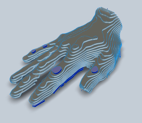
Fixed, thickened final model
Following this procedure the object was ready to be laser cut and constructed.
Model ready for laser cut
Subscribe to:
Posts (Atom)